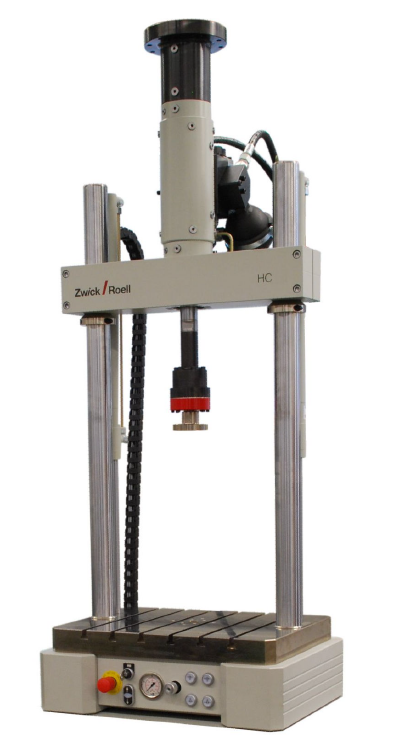
The servohydraulic testing machine Zwick HC 25 is used for dynamic materials and component testing. It can perform both monotonic and oscillatory loadings. Quasi-static testing is also possible. The main applications at our chair are medium strain rate characterization (~1 1/s), fatigue, and experiments at testing speeds or frequencies not possible with our electro-mechanical UTMs.
The HC25 is equipped with a liquid nitrogen cooled thermal chamber and can be complemented with different strain measurement systems, like strain gages, digital image correlation or video-extensometer.
Technical details
• Load cells: 2 kN and 25 kN with accelerometers
• Maximum Testing Speed: 400 mm/s
• Maximum Frequency: 100 Hz
• Temperature Range: -80 °C to 250 °C
• +-10V Digital-Analog-Converter: 2 Outputs and 1 Input
• Fixtures: Tension, Compression, Bending
• 2 x Strain Gages 120 Ohm
Contact person
Shima Norouzi, M.Sc.

The Universal Testing Machine (UTM) is a highly adaptable system for various standard material characterization tests. Our H&P Inspekt Table 100 serves as a cornerstone in our mechanical laboratory while offering various tests that yield fundamental mechanical properties of materials. These encompass but are not limited to bending, tensile, compression, combined loading compression, V-Notch Shear, In Plane Shear, Interlaminar Fracture Toughness (Modes I and II), Wedge Peel Test, Picture Frame, NOL Split Disk Test, and more. Moreover, the machine's testing capabilities can be expanded by integrating appropriate adaptors to conduct non-standard tests.
The UTM comes equipped with a default 100kN load cell and is compatible with alternative load cells—ranging from 10 kN, 2.5 kN, to 500 N—offering enhanced measurement resolution. Additionally, it integrates with various systems to measure strain, including strain gauges, Digital Image Correlation (DIC), and Videoextensometers, indispensable for the determination of stiffnesses and moduli.
Technical details
• Temperature range: room temperature
• Maximum force: 500 N, 2.5 kN, 10 kN, 100 kN.
• Maximum Testing speed: 400 mm/min
• Resolution of crosshead travel measurement < 0.0025 µm
• Tool connection: R20-8 and R60-30
• Two output signals +/-10V
• Max displacement 1125 mm
• Width between columns 510 mm
Contact person
Gabriel Eduardo Rojas Valenzuela, M.Sc.

The Universal Testing Machine (UTM) is a highly adaptable system designed for various standard material characterization tests. Our H&P electromechanical Inspekt Table 250, like the UPM 100, is a foundational part of our mechanical laboratory, offering a range of tests that uncover fundamental mechanical properties of materials. These tests include bending, tensile, compression, combined loading compression, V-Notch Shear, In-Plane Shear, Interlaminar Fracture Toughness (Modes I and II), Wedge Peel Test, Picture Frame, NOL Split Disk Test, and more. Furthermore, the machine's testing capabilities can be extended by integrating suitable adaptors to perform non-standard tests.
The UTM comes with a default 250kN load cell and supports alternative load cells - ranging from 10 kN, 2.5 kN, to 500 N - enhancing measurement resolution. Additionally, it integrates with various systems to measure strain, such as strain gauges, Digital Image Correlation (DIC), and Videoextensometers, indispensable for the determination of stiffnesses and moduli. In addition to the maximum load, the UPM 250kN electromechanical machine includes a thermal chamber, enabling testing under different temperature conditions.
Technical details
• Temperature range: -40°C to 350°C
• Maximum force: 500 N, 2.5 kN, 10 kN, 250 kN.
• Maximum Testing speed: 400 mm/min
• Resolution of crosshead travel measurement < 0.0025 µm
• Tool connection: R20-8 and R60-30.
• Two output signals +/-10V
• Max displacement 1125 mm
• Width between columns 610 mm and width in Temperature chamber 500 mm
Contact person
Gabriel Eduardo Rojas Valenzuela, M.Sc.
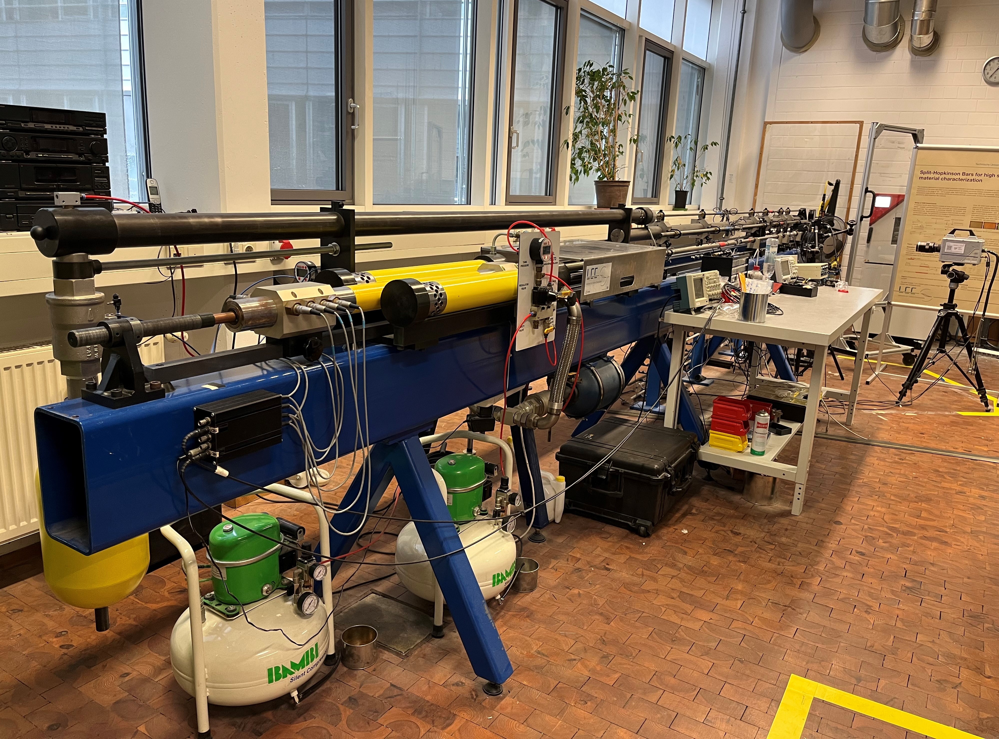
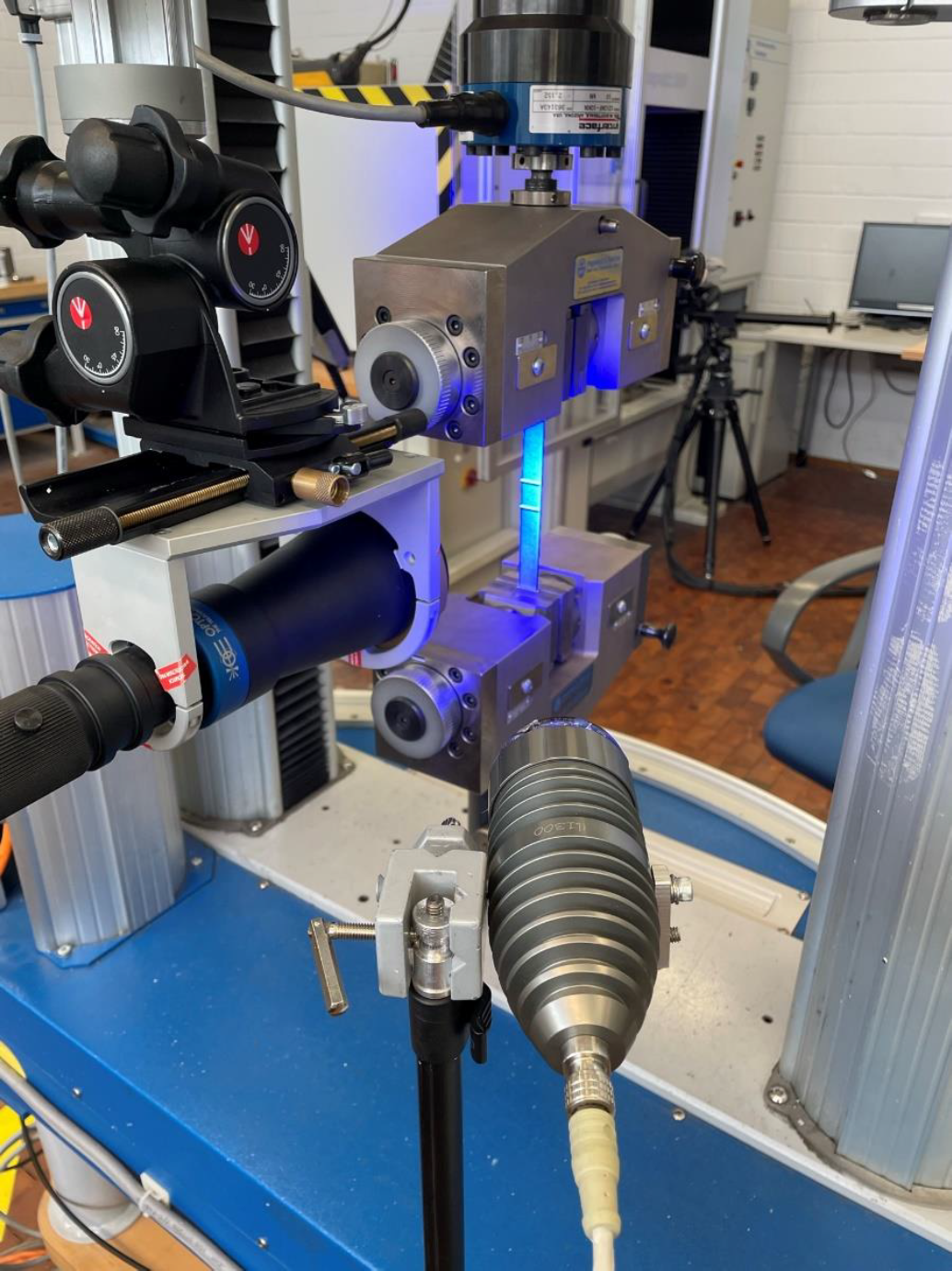
The Split Hopkinson Bar is an experimental device that uses the propagation of elastic waves to characterize the mechanical properties of a material under high strain rates. The facility at TUM-LCC offers the possibility to test under different loading conditions: tension, compression and torsion. In past research work, TUM-LCC has developed fixtures specially tailored to the characterization of composite materials. In combination with high-speed digital image correlation, important insights into the behavior under crash or impact loading can be gained.
Technical details
• Loading strain rates up to 1000/s
• Various load conditions (tension, compression and torsion)
• Titanium, Aluminum and steel bars in diameters from 16 mm up to 25 mm
• Pulseshaping using copper, brass or silicone pulseshapers
• Pulse duration up to 600 microseconds
Contact person
Marco Tönjes, M.Sc.
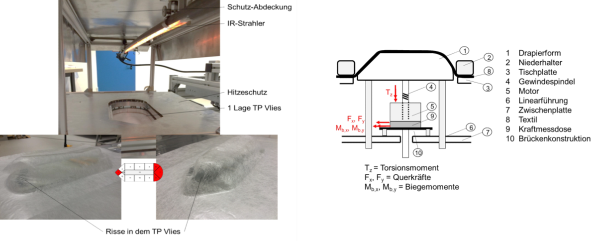
The LCC Pole Peak test stand was developed to investigate the draping behavior during preforming. The textile is fixed to a plane or table by a circumferential and segmented clamping device. The draping tool is moved upwards through the recess in the table and the textile is draped over the tool. The force required for this is recorded using a load cell. Comparative determination of process properties as well as validation of draping simulations are possible.
Contact person
Carina Schauer, M.Sc.
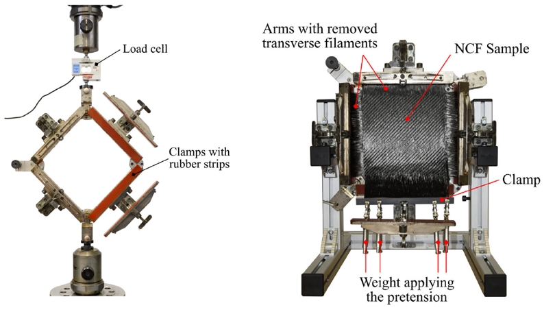
The picture frame test can be used to characterize the shear properties of dry weaves and non crimped fabrics (NCF). The test setup consists of a rigid frame with low-friction connecting elements. The textile sample is clamped in four clamping jaws of equal length and the assembly is inserted into the universal testing machine. The vertical pull of the square frame deforms it into a rhombus, exerting a direct and pure shear deformation on the textile sample.
Contact person
Carina Schauer, M.Sc.
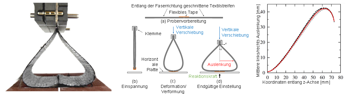
The bending stiffness of dry textiles can be determined using the LCC bending test rig. A curvature of the textile is generated over a defined area. The bending behavior can be determined on the basis of the deformed geometry, which represents the bending line in cross-section, and the measurement of applied forces. The bending line for the maximum deflection of the textile is recorded with a high-resolution digital camera. The averaged left/right deflection over the z-axis is shown as an example in the diagram on the right.
Contact person
Carina Schauer, M.Sc.
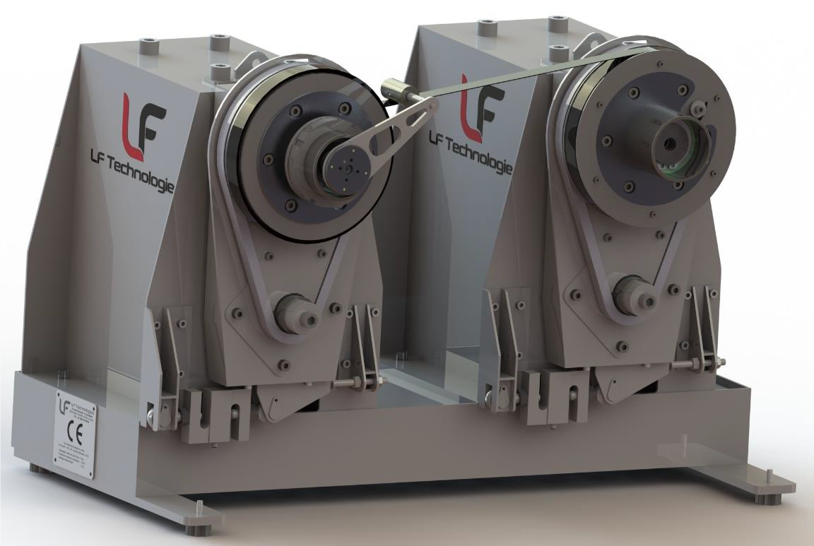
The Continuous Peel Test machine is used to perform peel tests on consolidated ring-shaped samples that have been manufactured for example using the winding process or Automated Fibre/Tape Placement.
Technical details
• Drum nominal diameter: 200 mm
• Max torque: 500 Nm
• Torque measurement precision: 0,25 Nm
• Resulting force precision: ≈ 2,5 N
• Rotating speed: 0 to 2 Rpm
• Max motor power: 400 W
Contact person
Jan Teltschik, M.Sc.
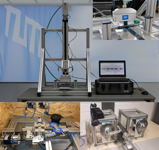
The tack of a pre-impregnated semi-finished product is a crucial material property for successful, efficient, and automated manufacturing. At the Chair of Carbon Composites of TUM, various test setups are available for determining tack properties.
The TUM Peel Tack test stand is an advancement of the Quick-Stick test, where the tack property of the semi-finished product is assessed following the AFP process. A motor pulls the sample upward at a 90° angle while the table is moved backwards, recording the force profile over the measurement duration. This method has yielded repeatable and precise tack results. The test stand can be transported without significant effort.
In the Double Drum Tack Test and Online Tack test stand, the sample (TowPreg or PrePreg tape) is compacted within the compaction unit using a pneumatically controlled roller onto the laying band. Subsequently, the sample is peeled from the laying band around a roller mounted on a swivel mechanism and wound onto the storage spool. The test mechanics are firmly connected to the substructure of the test stand with a force measuring cell, allowing the measurement of all forces acting on the test mechanics in the peeling direction.
Additionally, at the LCC, a sample tack test is conducted using the Anton Paar MCR302 rheometer. The rheometer enables precise control of compaction and sample temperature. The control software determines the temperature as well as the respective speed, force, and time of the compaction and pull phases. Throughout the entire measurement, the applied normal force and gap distance are recorded with a force measuring cell.
Technical details
• Depending on the load case, requirements, and boundary conditions
• Materials: Pre-impregnated fiber semi-finished products
• Test temperature: -10°C to 60°C
• Test speed: up to 0.5 m/s
• Defined environmental parameters
Contact person
Youssef Mraidi, M.Sc.; Sylvester Vogl, M.Sc.

The Differential Scanning Calorimetry (DSC) is a technique used to study the thermal properties of a wide range of materials. It measures the heat flow (heat capacity) into or out of a sample as it is subjected to a controlled temperature profile. By comparing the heat flow of the sample to a reference material, the equipment can provide valuable information about physical transitions like melting and crystallization, glass transitions, reaction kinetics, and more. This information is essential for understanding the thermal behavior and stability of substances, making the DSC a versatile tool in research, quality control, and product development across various industries.
Technical details
• Temperature range with the cooling unit RCS 90: -90 to 550 °C
• Sample weight: 0.5 to 100 mg (nominal)
• Purge gas: nitrogen
• Typical flow purge rate: 50 mL/min
• Autosampler with capacity for 50 samples available
• Typical maximum heating rate 20 K/min
• Modulated DSC
Contact person
Margarita Etchegaray Bello, M.Sc.

The viscoelastic behavior of polymeric materials, including fiber reinforced plastics can be described using different models, like Burgers, Maxwell, etc. The necessary material parameters can be determined using the DMA. The DMA is also the most sensitive technique to determine transition temperatures such as the glass transition temperature (Tg).
Technical details
• Max Force: 18 N / Min Force: 0.0001 N
• Displacement Resolution: 1 nm
• Frequency Range: 1 x 10^(-2) to 200 Hz
• Dynamic Deformation Range: ± 5 x 10^(-4) to 10 mm
• Temperature range: -150 to 600°C
• Isothermal Stability: ± 0.1
• Heating rate: 0.1°C to 20°C/min
• Cooling rate: 0.1 to 10°C/min
• Nitrogen Atmosphere
• Sample stiffness range: 100 to 10^7 N/m
Contact Person
Nikita Reinhardt, M.Sc.
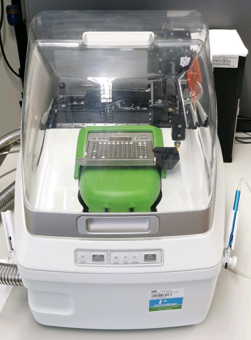
The DSC 8500 from Perkin Elmer is a performance-based HyperDSC, which is superior to conventional DSCs with its technology in areas such as isothermal crystallization, studies on polymorph/amorphous materials or highly sensitive measurements. With the help of an autosampler, samples can be measured consecutively and without operator influence. A UV module can be used to analyze light-initiated cured resins. This provides a better understanding of the kinetics of UV curing in order to optimize processing parameters.
Technical details
• Double furnance technology
• Autosampler for 96 samples
• UV photocalorimeter
• scanning rates up to 750 °C/min
• Ballistic in-situ cooling up to 2100 ºC/min
• Extremely fast readout rates (100 points/second) providing high data integrity
Contact person
Daniela Schreil, M.Eng.
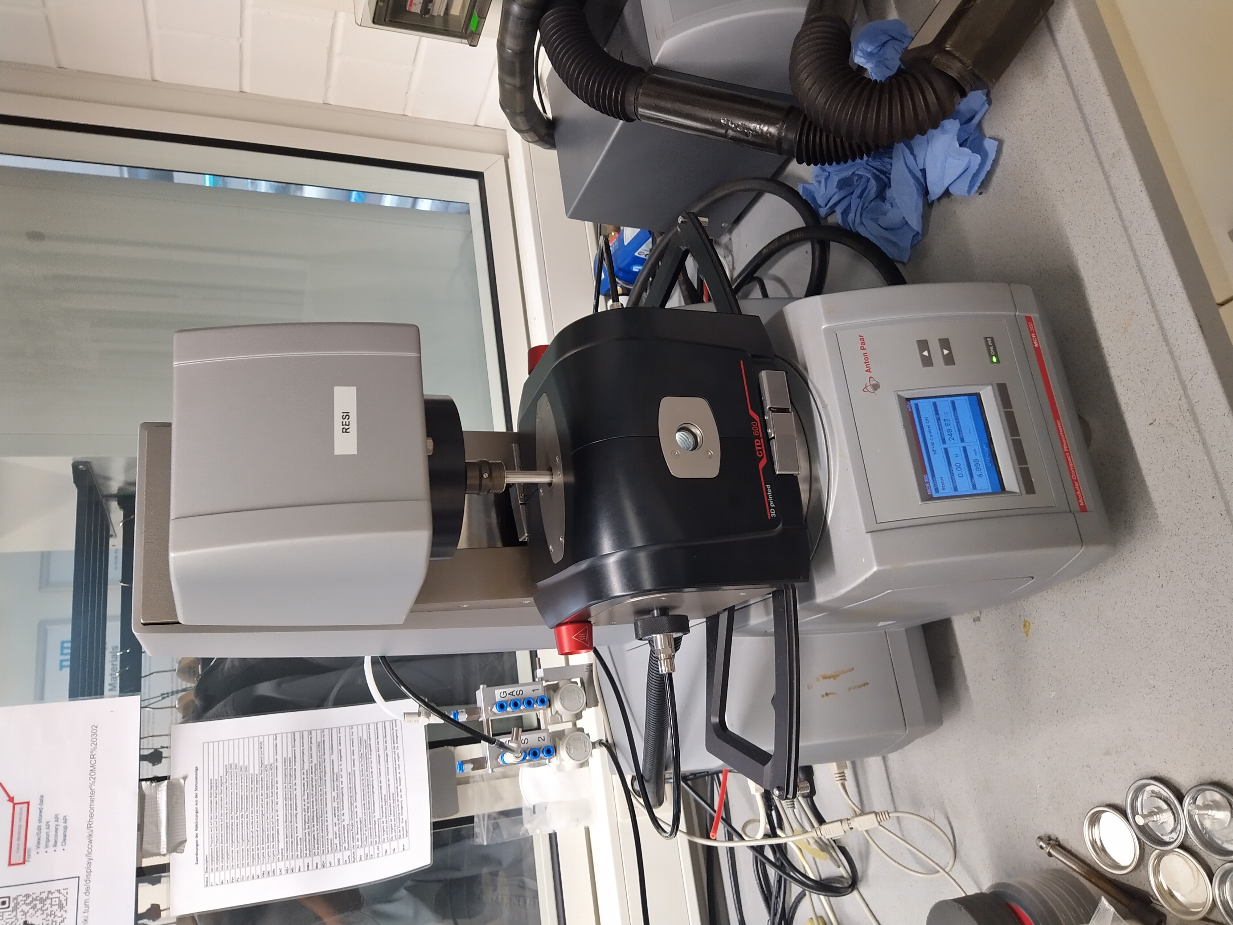
The Anton Paar MCR 302 is a laboratory equipment to measure deformation and flow behavior of liquid, solid & visco-elastic materials. This machine can be used to test either in a rotational or in an oscillating procedure. The machine's hoist motor additionally allows measurements in normal direction (e.g. tack or compaction measurements). At the LCC a broad variety of testing geometries & different temperature management systems is available to ensure a multitude of testing scenarios.
Technical details
• Temperature range: -150 °C – 600 °C
• Maximal heating rate: 60 K/min
• Maximal cooling rate: 50 K/min
• Available measuring configurations:
- Plate-Plate
- Cone-Plate
- Torsion bar
• Testing under inert gas possible
Contact person
Christian Jäger, M.Sc.
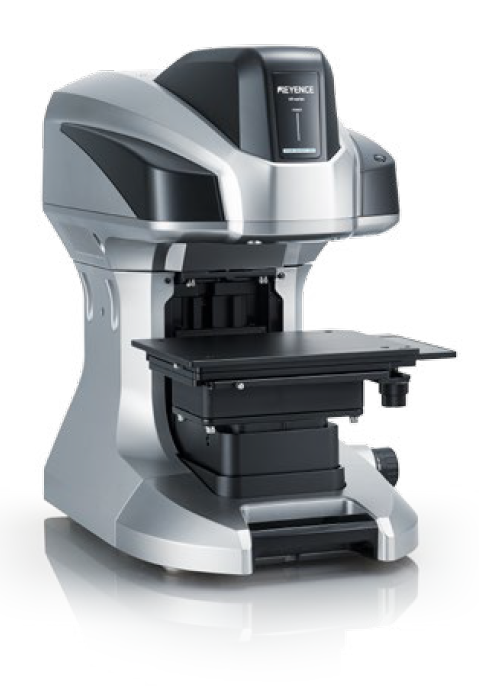
The Keyence VR5000 3D optical profiler enables contactless and precise surface measurement and analysis. Thanks to the quick and easy handling, e.g. the roughness of several test specimens can be determined fast and precisely.
Technical details
• Measuring area: 200 mm × 100 mm × 50 mm
• Differences of up to 1 µm detectable
• Profile, volume, flatness, roughness can be determined
• 3D visualization of the surface
Contact person
Matthias Feuchtgruber, M.Sc.
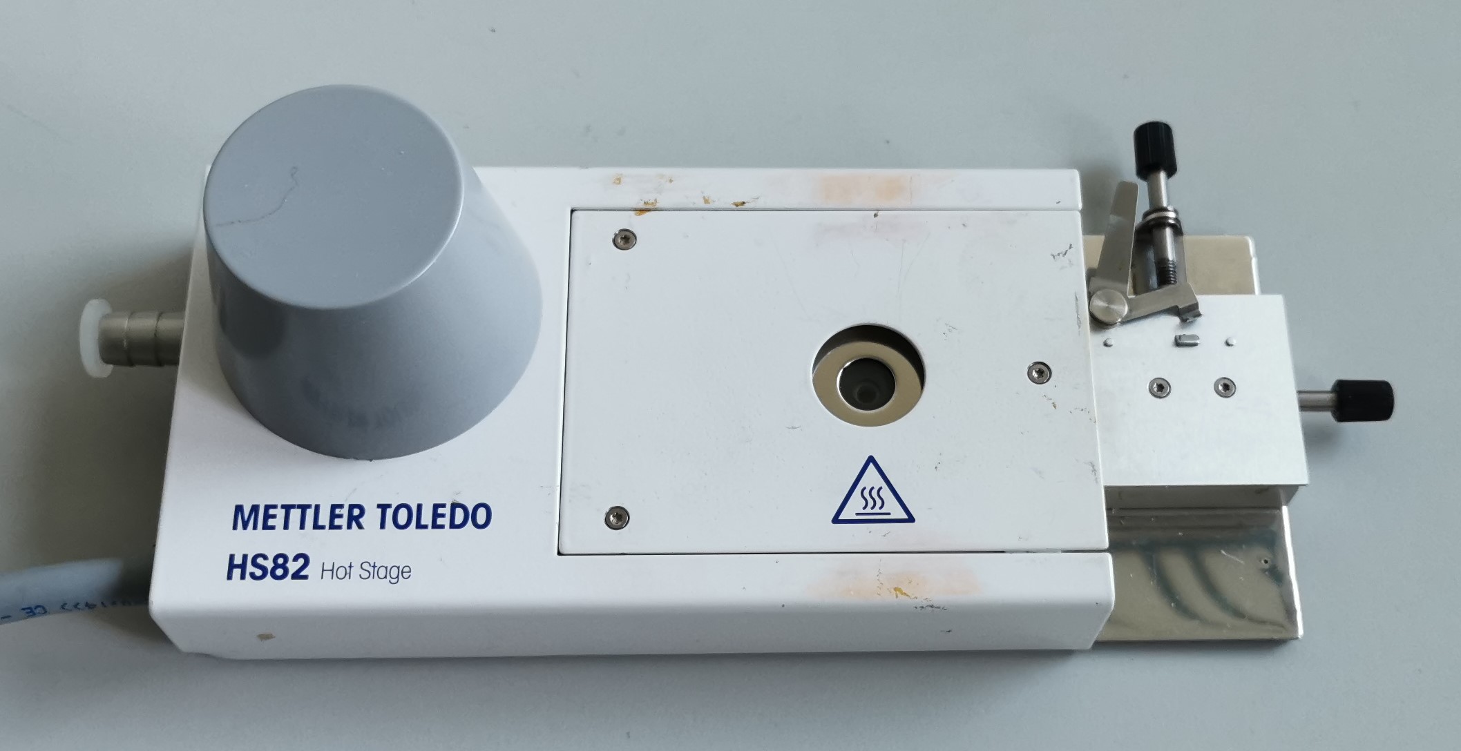
The hot stage enables samples to be tempered in the smallest of spaces and, together with microscopes, one can optically analyse the temperature behaviour of materials and temperature transitions.
Technical Details
• Temperature range: RT to 375 °C (with liquid nitrogen cooling: -90 °C to 375 °C)
• Temperature accuracy: ± 0.4 °C and ± 0.8 °C (depending on temperature range)
• Heating rate: 0.1 K / min to 20 K / min
• Sample carrier dimensions: 76 mm x 19 mm x 1 mm
• Field of vision: circle with 2 mm diameter
• Working distance sample to objective: min. 7 mm
• X-Y stage: max. 13 mm displacement
Contact person
Daniela Schreil, M.Eng.
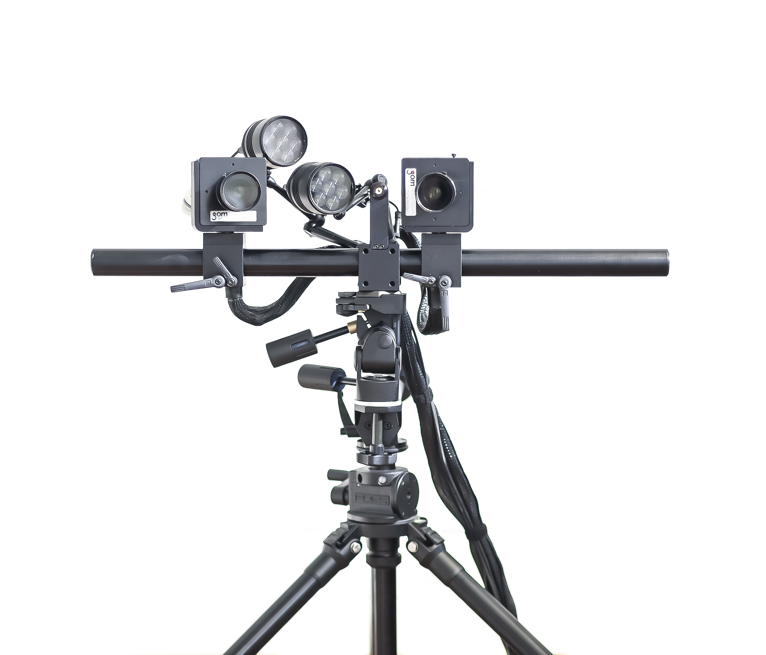
Digital Image Correlation is a full-field strain measurement system. In a stereoscopic configuration like that of our GOM ARAMIS 4M, it is possible to determine an object´s shape and deformation in three dimensions at different stages, provided that the surface has a high contrast, random, and isotropic texture. With our flexible basis, we can adapt the distance and orientation of the cameras to adjust the field of view to each object or sample, taking maximum advantage of the resolution. The ability to simultaneously record analog signals renders our system valuable in the mechanical characterization of composite materials. The system is particularly useful for examining strain concentrations and heterogeneous or coarse fiber architectures.
Technical details
• Resolution: 4 Megapixels, 2350 x 1750 Pixels.
• Frame Rate: 60 Hz at full resolution. Higher frequencies are possible with partial sensor use.
• Measurement Volumes: From 15 mm x 10 mm up to 200 mm x 150 mm
• Objectives: 50 mm and 100 mm focal lengths.
• 500 mm and 800 mm support bars.
• +-10 V Digital-Analog Converter. 8 Inputs and 4 Outputs
• External Triggers
Contact person
Luciano Avila Gray, M.Sc.
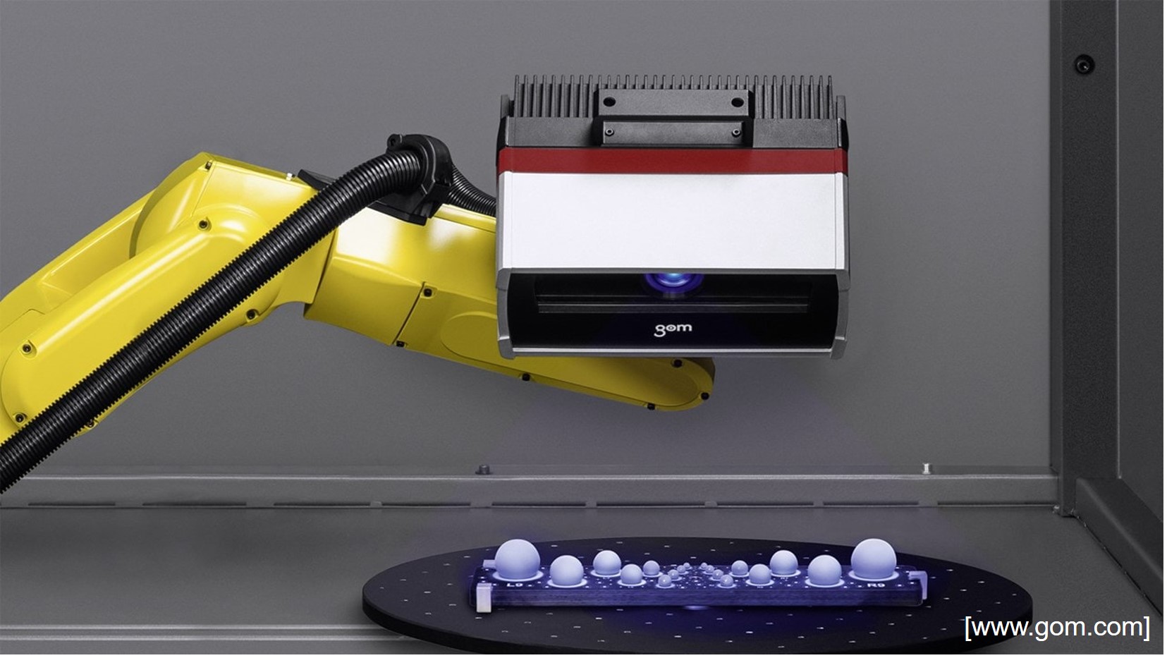
The ATOS Capsule is an optical precision measuring machine for full-surface detection and digitisation of component surfaces. Precise stripe patterns are projected onto the object surface and recorded by two cameras according to the stereo camera principle. The ATOS projection system is used for quality assurance of small to medium-sized components and is characterised by high precision for fine details.
Technical details
• Assembly: turn table with lift, tripod
• 3 sensor configurations available:
o MV70: Volume 70 x 50 x 40 mm³, focal length 50 mm, resolution 0,021 mm
o MV200: Volume 200 x 140 x 140 mm³, focal length: 20 mm, resolution 0,058 mm
o MV320: Volume 320 x 240 x 230 mm³, focal length: 12,5 mm, resolution 0,096 mm
Contact person
Fabian Diemar, M.Sc.
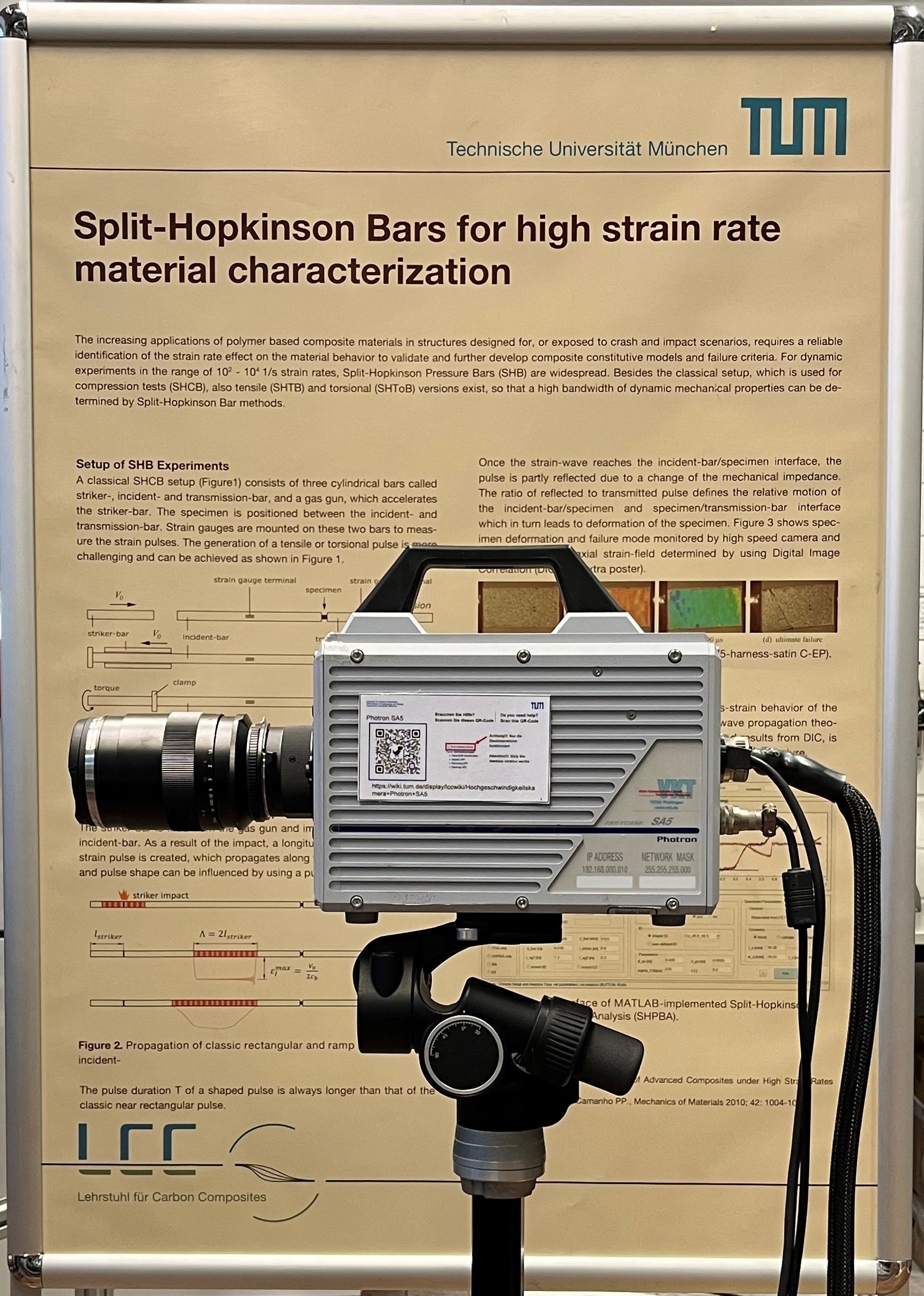
The high-speed camera Fastcam SA5 from the manufacturer Photron offers high-resolution image recordings at extreme speeds. It enables optical strain measurement using digital image correlation under dynamic loads. By using the external trigger function, the optical strain can be recorded synchronized with the mechanical stress. At the TUM-LCC, this setup is used, for example, to characterize the crash-relevant, strain-rate-dependent material behavior of composite materials.
Technical details
• 1024 x 1024 pixel at a frame rate up to 7000 fps
• Up to 775000 fps at reduced resolution (128 x 24)
• Up to 1 microsecond shutter time
• Trigger function for synchronized data recording with other measuring systems
• Monochrome 8 and 12 bits intensity resolution
• Objective Mounts: G type F-mount, C-mount
• Available Objectives: Zeiss Makro-Planar T* 2/100 mm, telecentric objectives
• CMOS image sensor with 20 micrometer pixel
Contact person
Marco Tönjes, M.Sc.
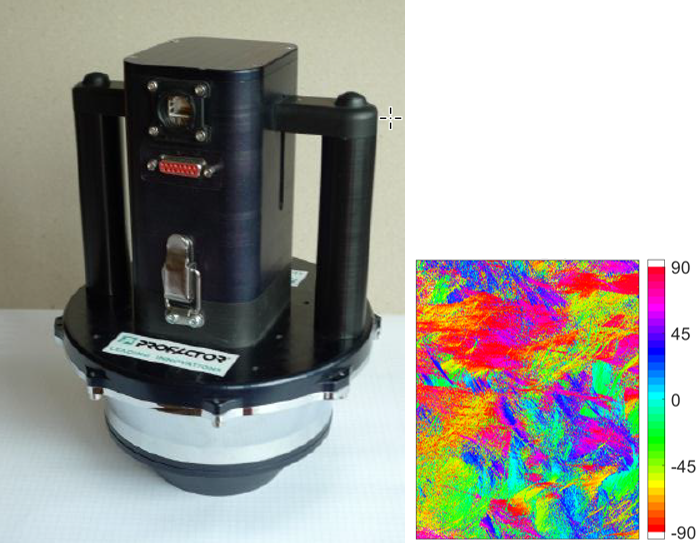
The Profactor sensor can detect the fiber orientation on the surface of endless and long fiber reinforced parts. The sensor is equipped with a fixture for the use in clamping jaws, allowing very precise placement with a robot. Depending on the resolution and detection area, two cameras are available.
Technical details
Camera 1
• Detection area: 55 x 55 mm
• Resolution: ca. 35 µm/pixel
• Exemplary application: SMC (see picture)
Camera 2
• Detection area: 25 x 30 mm
• Resolution: ca. 15 µm/pixel
• Exemplary application: NCF
Contact person
Anna Julia Imbsweiler, M.Sc.
The Video Extensometer is a camera-based strain measurement system used during mechanical tests. It consists of a camera (Baumer 12MP or Pike F-210 2MP), a lens (TC2M056-C), a light source (StarLight A0250), and the software “Real Time Strain Sensor” (RTSS) from Limess. The software can be linked to testing machine control systems such as LabMaster, so that the strain is measured synchronously with the testing machine data. The strain measurement is carried out using two marker stickers, which are applied to the specimen at a defined distance (10, 20 or 50 mm). The software recognizes the boundary of the transition from black to white on the stickers. The distance in pixels is then translated to mm based on the magnification and transferred to the testing machine. The measuring method is very robust if the light setting and application of the stickers are correct and is used as standard for tensile, bending and compression tests.
Technical details
• Camera-based, contactless strain measurement
• Two cameras for different applications (Baumer 12MP, Pike F-210 2MP)
• Telecentric objectives with 1x and 0,233X magnification
• Sampling rate of up to 150Hz
• Integration into testing machine control software, such as LabMaster, for synchronous strain measurement
• Digital-Analog-Converter to export and import testing data among other systems.
• RTSS: https://www.limess.com/en/products/rtss-videoextensometer
Contact person
Jan Seiffert, M.Sc.

The bar flow test setup was developed to investigate the flow characteristics of CFRPs. To this purpose, the setup is equipped with a pressure sensor placed underneath the compression cylinder, which records the pressure during the compression with the piston. Furthermore, eight temperature sensors are present along the flow channel, as well as further five temperature sensors at different locations on the setup. One of the main objects of research is the influence of the fiber orientation in long fiber reinforced plastics at the beginning of the process on the flow behavior, together with the reorientation of the fibers during the flow. The results of the measurements with the bar flow setup can be used as input for SMC and BMC process simulation. The test setup was developed to be adopted in the RUCKS Thermoforming machine of the LCC, and therefore, underlies the overall processing capabilities of the machine in terms of temperature, pressure and compression speed settings.
Technical details
• Dimensions flow channel (l x w x t): 450 mm x 30 mm x 5 mm
• Diameter cylindric charge opening: 30 mm
Contact person
Anna Julia Imbsweiler, M.Sc.

The Chair of Carbon Composites has a permeability laboratory for determining the impregnation properties of fiber textiles. With the help of the permeability values determined, different textiles can be compared and data for the input of simulations of the filling process can be obtained. Various test rigs are available for measuring permeability in in-plane and in thickness direction in order to fully determine the permeability tensor. The test rigs have already been used in several international benchmark studies and are compliant with existing standardization regulations.
Technical details
• 2D in-plane test stand for two-dimensional determination of the unsaturated permeability in in-plane direction
• 1D out-of-plane test stand for saturated permeability measurement in thickness direction
• 1D test stand for one-dimensional determination of saturated/unsaturated permeability in in-plane direction
• Test stand for the investigation of the compaction behavior of dry and wet preforms
• Viscosity measurement of the test fluid using rheometric analysis
Contact person
Maximilian Steinhardt, M.Sc.
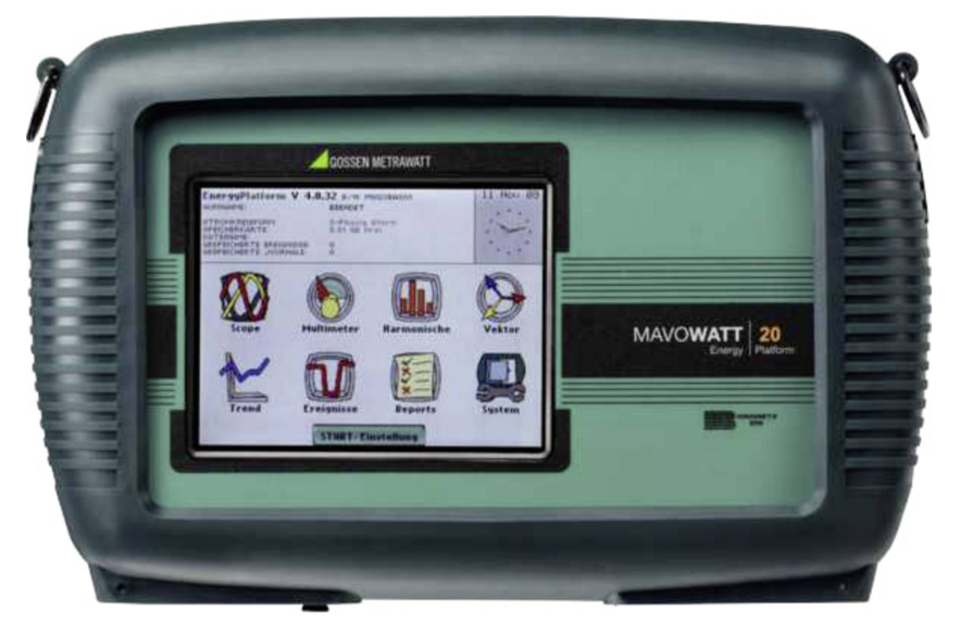
The MAVOWATT 20 is a portable, hand-held, eight-channel demand and energy meter/monitor. This power instrument is designed with a color LCD using touch screen. It can monitor, record and display data on four voltage channels and four current channels simultaneously. The MAVOWATT 20 is designed to conduct a complete demand and energy audit of a facility, a distribution circuit, or an individual piece of equipment.
Technical details
• 8 measurement inputs (4 voltage and 4 current)
• Alternating and direct voltage can be measured
• Accuracy: 0.1% for voltage and current
• Resolution: 256 samples per period, continuous recording
• Data storage media with up to 32 GB
• 3 hours with rechargeable battery
• CO2 footprint calculator
Contact person
Jan Teltschik, M.Sc.

The fiber friction test rig allows measuring the filaments protruding from a yarn before and after an interaction that damages the yarn. The increase in protruding filaments can be used as a measure of damage. In the interaction zone, the yarn can be exposed to various influences, such as another yarn running transversely to simulate the braiding process and the fiber damage occurring there. Additional interactions (bending, spreading, etc.) can also be replicated. Thus, the test rig provides a means to better understand and minimize damage processes during yarn processing.
Technical details
• Yarn Tension: 3N - 50N
• Speed: 1 - 10 m/min
• Inline Detection of Fiber Damage
Contact person
Youssef Mraidi, M.Sc.